We will choose the following inputs \& outputs: SW0 (J6) for A input SW1 (H5) for B input SW2 (H6) for C input SW3 (G4) for D input LEDG0 (J1) for X output 1. For this lab, we will be using switches 0-3 and a single LEDG output. Part I: Review the DE0 pin assignments found in section Appendix A: DE0 Pin Assignments. Previous projects can be opened by using File > Open Project.

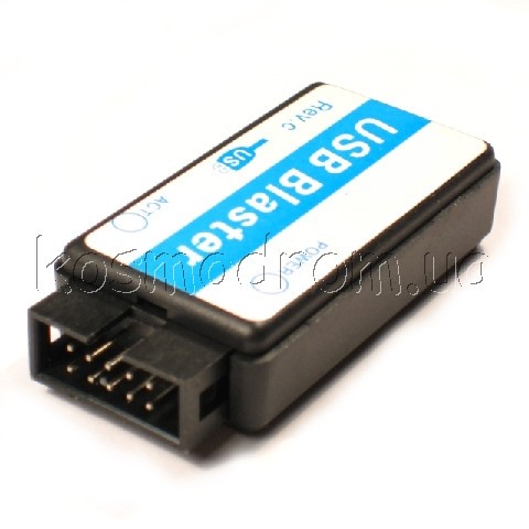
PROCEDURE Ensure that Lab 1 has been completed. ECET146 Lab Manual, Quartus II Common Activities NOTE: Ensure that the device drivers for the Altera DE0 development board have been installed successfully prior to beginning this lab. Getting Started with Altera DE0 Board.pdf (on Blackboard) b. Pre-lab - Reference the following documents: a. Students will use the Boolean1 program from Lab 1 Part 1, switches and LEDs to test the digital design. For the remainder of this course, being able to program designs to the FGPA is a critical function.

ogramming the DE0 OBJECTIVES The purpose of lab 2 is to demonstrate the steps necessary to program the Altera DE0 Development Board.


 0 kommentar(er)
